Communication and sharing promote growth
Joining Hands for Development!

The battery pack is a key component of new energy vehicles, energy storage cabinets and containers. It is an energy source through the shell envelope, providing power for electric vehicles and providing consumption capacity for energy storage cabinets and containers. In combination with actual engineering needs, this article summarizes the key points of profile design for battery packs by analyzing the requirements of mechanical strength, safety, thermal management and lightweight of battery packs.
1-Battery pack housing design requirements
a.Mechanical strength, vibration resistance and impact resistance. After the test, there should be no mechanical damage, deformation or loosening of the fastening, and the locking mechanism should not be damaged.
b.Sealing: The sealing of the battery pack directly affects the working safety of the battery system. It is usually required to reach IP67 protection level to ensure that the battery pack is sealed and waterproof.
c.The design of the battery pack shell needs to take thermal management performance into consideration and ensure that the battery operates within an appropriate range through appropriate thermal management design.
d.For installation and fixation, the shell should have space for nameplate and safety signs, and reserve sufficient space and fixed foundation for the installation of acquisition lines, various sensor elements, etc.
e.e. All connectors, terminals, and electrical contacts of non-polar basic insulation should meet the corresponding protection level requirements when combined.
f.Lightweighting: Lightweighting of the shell is of great significance to improving the energy density of the battery pack. Aluminum alloy is light in weight and high in quality, making it the most feasible choice at present. The lightweighting level can be improved through appropriate extreme design in combination with actual applications.
g.Durability: The design life of the battery pack shell shall not be less than the service life of the overall product. No obvious plastic deformation should occur during the use cycle. The protection level and insulation performance should not be reduced. The structure should be easy to maintain, including the layout of nameplates and safety signs, and protection of connectors.

Figure 1 Typical aluminum alloy welded battery pack shell
2-Typical aluminum alloy battery pack shell solution
Commonly used aluminum alloy materials for battery pack shells include 6061-T6, 6005A-T6 and 6063-T6, etc. These materials have different yield strengths and tensile strengths to meet different structural requirements. The strength of these materials is: 6061-T6>6005A-T6>6063-T6.

At present, the battery pack shell forming solutions include aluminum profile welding, aluminum alloy casting, cast aluminum plus profile aluminum, stamped aluminum plate welding, etc. The aluminum profile welding solution has become the mainstream choice due to its flexibility and processing convenience. As shown in Figure 1, the shell is mainly composed of an aluminum alloy profile frame and an aluminum alloy profile bottom plate, which are welded using 6 series aluminum alloy extruded profiles. The aluminum alloy casting solution is regarded as the future development direction due to its simplified process and cost reduction potential.
3- Profile section design
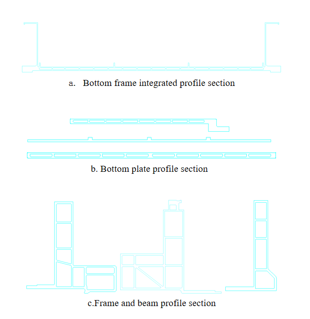
a. Section size and complexity: The section size of the profile is measured by the circumscribed circle. The larger the circumscribed circle, the greater the extrusion pressure required. The section of the profile is usually composed of multiple cavities to improve the structural rigidity and strength. Usually, the frame, middle partition, bottom plate, beam, etc. adopt different section designs to adapt to different structural and functional requirements.

Figure 2 Typical aluminum alloy profile section
b. Aluminum profile wall thickness: The minimum wall thickness of a specific aluminum profile is related to the profile circumscribed circle radius, shape and alloy composition. For example, when the wall thickness of 6063 aluminum alloy is 1mm, the wall thickness of 6061 aluminum alloy should be about 1.5mm. The extrusion difficulty of the same section is: 6061-T6>6005A-T6>6063-T6. In the design of battery pack profiles, the frame profile is usually made of 6061-T6 aluminum alloy material, and its typical section is composed of multiple cavities, and the thinnest wall thickness is about 2mm; the bottom plate profile is also composed of multiple cavities, and the material is generally 6061-T6, 6065A-T6, and the thinnest wall thickness is also about 2mm; in addition, in the design of the bottom plate load-bearing tray and bottom plate liquid cooling integration, the bottom plate generally adopts a double-sided structure, the bottom plate thickness is generally 10mm, and the wall thickness and the inner wall of the cavity are about 2mm.
c. Tolerance of profile cross-sectional dimensions: The tolerance of cross-sectional dimensions should be determined based on the processing allowance of the aluminum profile, the conditions of use, the difficulty of profile extrusion, and the shape of the profile. For some aluminum profiles that are difficult to extrude, the shape can be changed or the process allowance and dimensional tolerance can be increased to reduce the difficulty of extrusion and extrude aluminum profile products that are close to the requirements, and then they can be reshaped or processed to meet the use requirements.
In addition, when designing the profile section, it is necessary to consider the specific requirements of different welding processes for joints, grooves, wall thickness, etc.
We will regularly update you on technologies and information related to thermal design and lightweighting, sharing them for your reference.
Thank you for your attention to Walmate.